How to Use 3D Scanning for Reverse Engineering
Have you ever needed to replace a component but no digital model exists? Or have you needed to create a part that interfaces with a part with no documentation? This is where Reverse Engineering comes into to play. With the advent of 3D scanning, Reverse engineering has become more efficient and precise than ever before. In this article we’ll take a look at what reverse engineering involves, the advantages of 3D scanning, and the role of 3D reverse engineering software.
What is Reverse Engineering?
Millions of parts have been manufactured over time, and relatively few remain relevant for more than a few years. But those that do are often part of important systems and assemblies, so they are worth preserving. The older the system is, the less likely its original designs are available. There may have been physical documentation that has been lost or digital files that were deleted. Or a part may have been produced by a company that no longer exists. Reverse engineering allows one to recreate the part’s 3D CAD file by working backward from a physical part, bringing it back to life in digital form.
3D scanning plays a critical role in reverse engineering by enabling the precise capture of the geometry of an existing part, and converting it into a digital format for further analysis, modification, or replication. 3D scanning offers advantages over traditional measurement methods around accuracy, efficiency, and the ability to capture complex geometries.
What are the Steps in the Process of Reverse Engineering?
SCANNING: 3D scanning is the fastest, most accurate way to capture a component’s complete geometry. You may need to prep the part with a powder spray to eliminate reflections that can compromise scan quality. 3D scanners operate using lasers, structured light, or photogrammetry, ensuring the object remains untouched during scanning. This may be especially important for fragile, antique, or sensitive components where physical contact could cause damage. 3D scanners work on a wide range of objects, from large to small sized objects, as well as simple to complex geometries.
Accuracy is a cornerstone of effective reverse engineering.
The Artec Point captures complex surfaces with incredible accuracy and repeatability.
Processing & Meshing: The scanned 3D file is often called a point cloud, or a digital representation of the part’s shape. These points can be connected into triangles, known as a mesh. To prepare the mesh for conversion to a 3D CAD, it may need to be refined: if you scanned the part multiple times from different angles, these separate scans are aligned and fused together. This step also includes the removal of unnecessary points or artifacts that may have been captured, and its gaps filled in. This step is often performed with software that accompanies the scanner, such as Artec Studio.
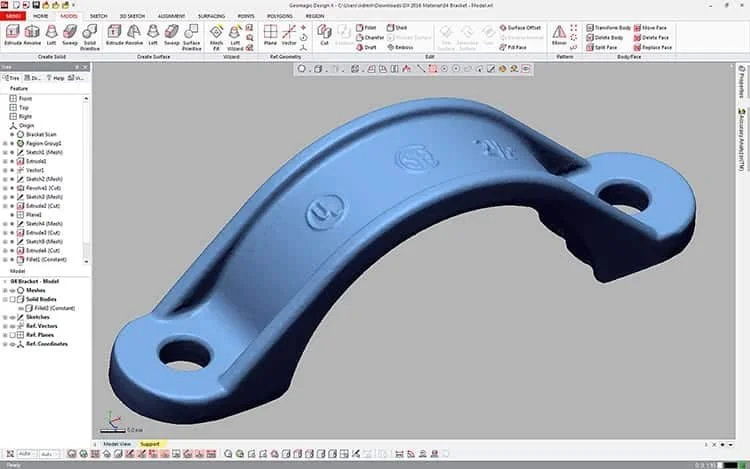
Reverse Engineering Software - Importing the Mesh File: To turn a mesh into a usable CAD file, you’ll need reverse engineering software, such as Artec Studio, Geomagic DesignX or Quicksurface, that enables import of the mesh, and for surfaces to be created based on the shape of the triangle model. Keep in mind, some of these tools only work with simple, flat surfaces. Make sure to choose software that can handle meshes of a complex shape.
Reverse Engineering Software - Converting the Mesh to CAD Format: To turn a mesh into a usable CAD file, the reverse engineering software enables surfaces to be created based on the shape of the triangle model.
After the mesh is imported, its surfaces need to be built so they can be edited. There are three ways to do this. Semi-automatic surfacing captures most surfaces automatically, then you finish the process manually. Automatic surfacing takes care of the whole process, but gives you less flexibility to make changes to the model later. Manual surfacing enables total flexibility and adjustment by the user, but it’s also the most time-consuming method.
At this point, you’ll have a usable 3D model that engineers can interact with, whether that means adding new features, adjusting existing features, or analyzing the model as it stands. For best results, a high-quality 3D scan is paramount.
What are the Benefits of Using 3D Scanning for Reverse Engineering?
Manufacturers who want to reverse engineer a part need an accurate 3D model. 3D scanners, like those offered by Artec3D and Scantech, offer the easiest way to capture the geometry of any object, and the data they deliver can be processed and edited to improve or fix broken sections of the original.
Key advantages of using 3D scanners for reverse engineering include:
Complexity: 3D scanners measure millions of points on each surface, so they can handle very intricate parts.
Speed: 3D scanners capture data much faster than contact-based techniques.
Completion: 3D scanning provides a comprehensive picture of the part, so you can capture elements of the part that have worn down, failed, or otherwise deviated from their original design.
Convenience: 3D scanners are easy to transport, so they can be used anywhere.
Of course, a 3D scan by itself doesn’t enable reverse engineering. The scan has to be transformed into a CAD model using reverse engineering software. Ideally, the software you choose should be able to quickly process large data sets, create complex hybrid 3D models, and connect directly with your CAD environment.
At My Engineering, WE SPECIALIZE IN PREMIUM PRODUCTS AND SERVICES. We stand behind our products and we support our clients. We are experienced in the field of 3D Scanning, and we know what works best to get the results you need.


